We use cookies to make your experience better. To comply with the new e-Privacy directive, we need to ask for your consent to set the cookies. Learn more.
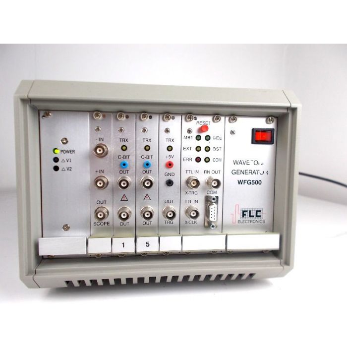
WFG500 Waveform Generator from FLC Electronics, Manual and Software available
£0.00
Out of stock
SKU
H045
WFG500 Waveform Generator from FLC electronics
Manual and Software available
The software Can be downloaded from the Manufacturers web site.
http://flcelectronics.com/software.html
The multichannel, high voltage, computer controlled Waveform Generator WFG600 is an exceptional instrument designed primarily for experiments on addressing liquid crystal devices and is most suitable for all applications where synchronized trains of pulses with variable width and amplitude are required.
The WFG500 Waveform Generator delivers arbitrarily placed trigger-pulses and may itself be triggered externally. It can operate in one continuous and two burst modes. The summing module produces a low-voltage superposition of two chosen waveforms. Due to the unique double memory concept the waveforms can be modified during operation. Each output channel contains a very fast high-voltage amplifier.
The WFG500 Waveform Generator is controlled by a PC-Windows® computer(NT, 2000, XP, Vista, 7) or a Macintosh® running OS9. A standard serial interface is used for communication. Waveforms are graphically edited on the screen. Two waveforms and their superposition are displayed simultaneously, others being accessible via pop-up menus. Functional relations between pulses in the waveforms and between time-steps can be programmed-in to avoid repeated manual adjustments. Waveforms may be joined in groups to allow synchronous amplitude adjustments. Waveform data can also be exchanged with a spreadsheet program.
The WFG500 Waveform Generator, when New, is delivered with software for Windows and Macintosh environments, and with VI library for LabVIEW®. The software can be freely downloaded for evaluation. All elements of the user interface are explained on the snapshot of Macintosh screen and Windows screen.
Differences between WFG600 Waveform Generator and a typical Arbitrary Waveform Generator
An Arbitrary Waveform Generator (AWG) usually has only one output channel. The WFG600 Waveform Generator is a multichannel device.
The AWG's output-signal is a low voltage one and an amplifier is most often required. The WFG600 Waveform Generator has a very fast high-voltage amplifier built into each channel. Output amplitude is independent of the load (within the current limits).
All AWGs construct their waveforms from many equally spaced points. Such approach suits well generation of analogue signals like "heart beat simulation." The WFG600 Waveform Generator is designed to produce pulse-trains and each pulse has its own width. Waveforms may thus be created and altered faster, simpler and require less memory space.
In an AWG, changes are put directly into the waveform being generated, which results in some transient states. To prevent this, the WFG600 Waveform Generator incorporates two equivalent memory sets. At any time, one of them is used exclusively for waveform generation and is not affected by the editing procedure. The changes are instead directed to the other memory set. When the new waveform is prepared and the old one has reached its end, the memory sets are interchanged. Such memory swapping does not cause any delay and is performed simultaneously in all channels.
The available software for AWGs is very troublesome to use when creating pulse-trains. The hardware and software of the WFG600 Waveform Generator have been developed concurrently and optimized for this purpose. One can, for example, define logical relations between pulses and complex changes can be performed by a single mouse click.
Operating modes:
- Continuous
- Continuous with frame counting
- Burst one frame
- Burst one frame with waveform inversion
- Burst N frames
- Burst N frames and roll waveforms
- Script - programmable multiple burst with waveform rolling
- Script - programmable multiple burst with reloading waveforms
- Multiplexing an electrode matrix
Outputs:
Two BNC contacts for the high-voltage output on each channel
Pulse-related control bit (TTL level) individually on each channel
Oscilloscope trigger pulse (TTL level, multiple trigger points possible)
"Generator running" signal (TTL level)
Low-voltage superposition of two chosen waveforms (for monitoring on oscilloscope)
Inputs:
External clock
External trigger
Run/Hold control
Forward/Reverse control
Computer control
serial (RS232)
57600 baud, 8 bit, N, 1
Timing
Time-base clocks:
20 MHz (crystal controlled, 1 time unit = 50 ns)
1 MHz (crystal controlled, 1 time unit = 1 µs)
1 kHz (software controlled, adjustable in multiples of 1 ms)
external clock (TTL, square wave)
Minimum pulse width:
2 time units
Pulse width resolution:
2÷32767 clock units wide (15 bit resolution). The width of each pulse can be set individually.
Maximum number of pulses:
12288
Amplitude
Maximum:
±100 V, 185 mA (other configurations are available, see Short description)
Output impedance:
< 0.1 ohm
Load:
resistive || capacitive
Slew rate:
300 V/µs at 400 pF load
Resolution:
12 bits (or 50 mV at the high voltage output)
Accuracy:
±1LSB or <2% of setting, limited by settling time. Settled amplitude is independent of the load within the current limits
Note:
Each output channel corresponds to our F10A high volatge amplifier. Please see F10A page for full specification and bandwidth graph.
Operating conditions~:
Ambient Temperature:
0°C to 40°C (operation), 0°C to 60°C (storage)
Relative Humidity:
up to 90% (operation), 30% to 50% (storage)
Warm-up Time:
none
Power Requirements/:
220/230 V, 50÷60 Hz
Country of Origin/:
Sweden
Serial Number: 016043
| SKU | H045 |
|---|---|
| Availability | Out of Stock |
| Condition | Used |